


Link to HOME

Overview
So far we have only looked at characteristic qualities of the piezo effect. In order to make also a quantitative analysis we need numbers, for example to compare materials or to predict a sensitivity of an accelerometer.
In the world of piezoelectricity most often the following Symbols are used:
E = electric field
D = electric displacement
T = mechanical stress
S = mechanical strain
s = elastic compliance, the inverse value of the Young’s modulus Y (s=1/Y)
ε = permittivity (sometimes the letter K is used for the relative permittivity)
d = piezoelectric charge constant
g = piezoelectric voltage constant
k = coupling coefficient
The number that quantifies the piezoelectric effect of a material is called piezoelectric constant. Most important for our applications is the piezoelectric charge constant d that tells us how well the material converts mechanical stress into electrical charge.
d = P / T the dimension of d is [d] = C / N (Coulombs per Newton)
or more conveniently [d] = pC / N (Pico Coulombs per Newton)
P is the polarization [P ] = C / m²
T is the mechanical stress [T ] = Pa = N / m²
The piezoelectric charge constant d indicates the polarization P generated per unit of mechanical stress T applied to a piezoelectric body.
However this simple equation is only correct when the temperature remains constant, the initial electric field equals to zero and when we have a uniaxial stress condition, meaning either a single axis compression or tension or a single axis shear condition.
(For more detailed information refer to the red page)
An interesting detail of the charge constant is apparent when we look at its dimension: It is independent of the surface area, which means that the charge we collect from a piezo electric body depends only on the force we apply, not on the size of the piezo!
Directions Subscripts
-
The directions of x, y and z for general quantities are represented by 1, 2 and 3
-
The shear stress about the axes 1, 2 and 3 is represented by the numbers 4, 5 and 6 respectively
-
For piezo ceramics the direction of positive polarization is usually the 3-axis. (under compression, the polarity of the charge is identical to one of the initial poling field
The subscripts i and k mean:
i k
d

k = direction of mechanical action
i = direction of the electric field
= direction perpendicular to the electrodes
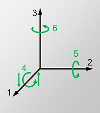
Axes to specify the piezoelectric constants
Examples of Subsripts
Piezoelectric Charge Constant [dik] = C/N
Compression Mode
d33 would indicate the polarization generated in the 3-direction per unit of mechanical compression stress (T) applied in the 3-direction to the piezoelectric body.
( hover with the mouse over the picture to apply a force)


Transverse Mode
d31 is the polarization developed in the 3-direction per unit stress applied in the 1-direction (all other external stresses = 0).

Shear Mode
d15 means the polarization developed in the 1-direction
per unit shear stress 5 applied (= shear around the 2-direction) when there are no other external stresses.
Note: The mechanical inputs above are uniaxial. Any other mechanical input (shear or compression) is equal to zero.

Piezoelectric Voltage Constant [gik] = Vm/N
g31 is the electric field developed in the 3-direction per unit stress applied in the 1-direction when there are no other external stresses.
The relation between the voltage constant and the charge constant is
d=εᵀg or g=d/εᵀ
(The superscript T indicates that this value is obtained at constant stress T )
Coupling Coefficient kik (./.)
k13 denotes the coupling coefficient between the mechanical energy input in the 1-direction and the energy converted in the 3-direction or vice-versa.
The electromechanical coupling factor k is the measure of the effectiveness with which a piezoelectric material converts electrical energy into mechanical energy, or converts mechanical energy into electrical energy.
converted energy
k² = –––––––––––––
input energy
Inverse Piezo Effect [dik] = m/V
d33 is the strain in the 3-direction per unit of electric field applied in the 3-direction, the piezoelectric body being mechanically free and the electric fields in the 1- and 2-direction are zero.
How can it be?
How can it be that once the dimension [d33] = m/V and once [d33] = C/N?
Let's have a look:
electrical: W = V∙A | A = C/s → W = V∙C/s
mechanical: W = J/s | J = N∙m → W = N∙m/s
V∙C/s = N∙m/s
V∙C = N∙m
C/N = m/V
Meaning, that both the dimensions are identical !
In the literature or material data sheets you will find d usually with two subscripts dik
Because of the anisotropic nature of piezoelectric materials their properties (elasticity, permittivity, charge constant etc.) are depending on the direction. Mathematically they are called tensor quantities. For this reason the constants are written with two subscripts which refer to the direction of the quantity.
To identify directions in a piezoelectric element, three orthogonal axes are used. These axes are named 1, 2, and 3, analogously to x, y, and z of the classical three-dimensional set of axes.
Material Constants and Condition Superscripts
In the literature or data sheets you will find expressions like sᴰ, sᴱ, εᵀ, εˢ etc. They require some further explanation. The superscripts to the symbols denote the boundary condition quantity which is kept constant.
Examples of Condition Superscipts
sᴱ11 = compliance for a (tensile) stress and related strain both in direction 1
at constant electric field (= electrodes short circuit).
sᴰ36 = compliance for a shear stress about the axis 3 and related strain in direction 3
at constant electric displacement (= electrodes open circuit).
εᵀ11 = permittivity for the dielectric displacement and electric field in direction 1
at constant stress (= mechanically free).
εˢ33 = permittivity in direction 3
at constant strain (= mechanically clamped )
Sensitivity of a Piezo Element

Most often when we use a piezo electric constant it is the sensitivity what we really want. I.e. the electric charge Q or the voltage V that we obtain when we apply a certain force F.
We remember the charge constant d was defined as polarization P per unit of mechanical stress T
d = P / T
P = Q / A (electric charge per surface area)
T = F / A (mechanical load per surface area)
so
d = Q / F or Q = d·F ( just need the adequate dik )
We know the charge is distributed over the surface, so this could lead to the feeling that increasing the surface would also increase the charge. However if we do this the force is also distributed over a larger area and the stress gets smaller proportionally.
As we have seen before the output charge is independent of the size of the piezo element.
To calculate the voltage sensitivity it gets a bit more complicated. We can obtain the voltage through the capacitance of the piezo element.
The voltage U of a capacitor C is given by U = Q / C
The piezo element is a parallel plate capacitor
with the surface A and thickness t.
It's capacity C is
C = ε · A / t
So the produced voltage by the force F becomes
d · F · t
U = –––––––––
ε · A
and with d / ε = g U = g · F · t / A
We see that the first part of the equation is analogue to the charge formula but it has got an extension, a “ form-factor ” t / A.
The output-voltage is therefore depending on size and shape of the piezo element !
The Pyroelectric Effect
Some of the piezoelectric crystals and all piezo ceramics possess a unique polar axis even in the unstrained condition. This results in a change of the polarization and appearance of an electric charge at the surface when the piezo is subjected to a change of temperature. This is called the pyroelectric effect. The pyroelectric coefficient p is defined as the change of the spontaneous polarization vector P with the temperature T.
p = dP / dT
p is also a vector and the scalar dimension is [p] = C · m⁻² · K⁻¹
So the spontaneous polarization of these piezo materials is not constant but varies with the temperature. Looking at the crystal grid of PZT for example we can imagine that the positive centre ion (red) slightly changes its relative position with respect to the negatively charged Oxygens (green) when the crystallite is subjected to a different temperature.

The total pyroelectric coefficient that appears at constant stress (= mechanically free) is the sum of a primary pyroelectric effect that would exist at constant strain (= mechanically blocked) and a secondary pyroelectric effect which is due to the thermal expansion of the piezo material.
This means the pyroelectric effect in reality is a quasi static charge which is in fixed relation to the temperature. The question remains why can we observe it only during a temperature change? This is because the internal resistance of the piezo element is not infinite and a small current flows from one electrode to the other and the pyroelectric charges disappear again. However, when the temperature changes, the charge does not have the necessary time to disappear.